Desert Hybrids Precision
R-Max CNC Router/Engraver/Plasma Cutter Plans
Home
Hot Rod Shop
Hot Rod Shop Tools
Sports Car Restoration
1952 Ford F1 Truck Project
1959 Dodge Truck Turbo-Diesel 4WD Conversion Project
1940 Ford Tudor Hot Rod Project
P-Max - "Pullmax Style" Reciprocating Power Hammer Plans
P-Max - "Pullmax Style" Reciprocating Power Hammer Deluxe Kit
P-Max - "Pullmax Style" Reciprocating Power Hammer Welder Series Kit
P-Max & Pullmax Tooling and Dies
Planishing Hammer Tooling and Dies
Power Hammer Tooling and Dies
Flow Forming Tool Holders
"Pullmax Style" Thumbnail Shrinking Die Plans & Construction Manual
R-Max CNC Router/Engraver/Plasma Cutter Plans
Preview P-Max - "Pullmax Style" Reciprocating Power Hammer Plans
English Wheel Plans
English Wheel Kits
English Wheel Parts
Hydraulic Tubing Bender Conversion Plans
1932 Ford Frame/Chassis Table Plans
Planishing Hammer Plans
Planishing Hammer - Medium Duty
Planishing Hammer - Heavy Duty
Planishing Hammer - Heavy/Medium Duty Combo
Planishing Hammer Kit
Deluxe Planishing Hammer Kit
Planishing Hammer Parts & Dies
Planishing Hammer Die Adapters
Planishing Hammer Deluxe CP Lower Die Set (26 piece)
Planishing Hammer Die Specs
Planishing Stainless Steel with Nylon Dies
Radius Gauge
Metal Shaping Resources
Harley Chopper Rigid Frame Welding Jig Plans
Harley Chopper Frame Jig Neck Cones
Harley Chopper Frame Jig Neck Cone Assembly
Orders
Blank page 1
R-Max CNC Router/Engraver/Plasma Cutter Plans
Blank page 3
Blank page 4
Blank page 5
Blank page 6
Blank page 7
Blank page 8
Blank page 9
Blank page 10
 

R-Max CNC Router/Engraver/Plasma Cutter Plans!


It's 2 Machines in One!! Simply Remove the Router Table and Replace the Router with the Plasma Torch to Convert from Wood Routing/Engraving to CNC Plasma Cutting

The Water Tray + Exhaust Draft System will Eliminate Over 95% of the Airborne Smoke and Contamination that is Normally Associated with Plasma Cutting!!


Manufactured by Desert Hybrids Precision Engineered Products, this professional set of plans and manuals provides all the information you will need to scratch-build your own R-Max - high quality CNC Router/Engraver/Plasma Cutter!

See More Photos of the R-Max!
Click on Photo Below to See Slideshow.

p-max016.jpg
Click on Photo to View Slideshow

These plans include over 150 full pages of CAD drawings, high resolution color photos, and text describing in great detail every aspect of building and setting up the R-Max CNC Router/Engraver/Plasma Cutter. The R-Max plans & construction manual will allow anyone with basic machining and welding skills to build this "R-Max CNC Router/Engraver/Plasma Cutter for about $800-900 parts/materials/electronics/software cost.

    • R-Max CNC Router/Engraver/Plasma Cutter Plans & Construction Manual: 137 pages
    • 43 Detailed CAD Drawings
    • Over 150 Full Color High Resolution Photos
    • Complete Parts/Materials List Including Part Numbers & Cost Breakdown

    Topics Covered Include

  • Step-by-Step Fabrication and Construction Procedure
  • Electrical Build
  • Software Programming
  • Sources for Motors, Bearings, Hardware, Electronics, Software
  • Manufacturer’s Names & Part Numbers
  • R-Max CNC Router/Engraver/Plasma Cutter Set-up & Adjustment
  • Optional Accessories
  • Alignment Procedures
  • Cost Analysis of Parts & Materials

Introduction

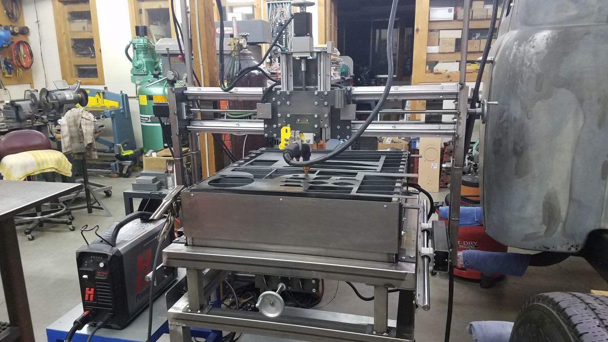
The R-Max CNC Router/Engraver/Plasma Cutter is designed to be a versatile, reliable, and accurate CNC machine. The R-Max is ideal for the small shop that requires CNC wood routing/engraving capability as well as CNC plasma cutting capability.

 The R-Max design is scalable to enable creation of a larger capacity machine if desired. The length and width can easily be extended by simply adding additional lengths of 20 mm fully supported linear rail.

 This set of plans and construction manual will allow anyone with basic machining and welding skills to build the R-Max CNC Router/Engraver/Plasma Cutter for less than $900 in parts and materials cost.This includes all motors, electronics, controllers, software, etc.

 The R-Max is constructed from commonly available materials and parts. This construction manual includes a complete parts list with prices as well as part numbers for many of the parts. There are detailed CAD drawings for all parts and assemblies, as well as many photos of the individual parts and assemblies.

 The Assembly Notes include many important details about building, assembling, and adjusting the R-Max. The R-Max CAD drawings, screen shots and parts list shown in this manual are also included as separate pdf files for increased clarity at higher resolutions.


Machine Specs


Designed & Manufactured By Desert Hybrids Precision Engineered Products

 Routing/Engraving Area:               25 in. x 27 in.

 Plasma Cutting Area:                      24.5 in. x 24 in.

 Z-Axis Travel:                                6 in.

 Router Table Size:                          36 in. x 40 in.

 Plasma Cutting Table Size:            27 in. x 31 in.

 Water Tray Size:                             26.5 in. x 31 in. x 4 in. Deep

 Exhaust Port Size:                          4 in. Diameter

 Table Leveling:                             Independent Leveling Adjustment

                                                        for Cutting Grate & Router Table

 Manual Motion Control:               Hand Wheels for X, Y, and Z                          

Overall Dimensions:                       50 in. x 44.5 in. x 43 in. Tall

 Machine Weight:                            Approx. 175 lbs.

 Max. Cutting Capacity:                  24.5 in. x 24 in. x 1 in. Thk. Plate Steel

 Max. Weight Capacity:                  Approx. 250 lbs.

 Max. Router Size:                           2.5 HP

 Primary Construction Material:    Steel/Aluminum

 Stepper Motor Type:                      NEMA 23

 Stepper Motor Torque:                  269 oz.-in. (280 oz.-in. optional)

 Linear Rails:                                    20mm Fully Supported

 Linear Bearings:                              Re-circulating Ball Bearing

 PC Interface:                                   Windows  USB

 Stepper Motor Control:                 Arduino UNO R3/GRBL v1.1

 Interface Software:                         Candle Version 1.1.7

 CAD/CAM Software:                     Fusion 360 or       AutoCAD/dxf2gcode        

 Mechanical Drive System:             0.5 x 10TPI    5-Start RH Precision Acme Lead Screws for X-Axis and Y-Axis

                                                          0.5 x 10 TPI      2-Start RH Precision Acme Lead Screw for Z-Axis

 Drive Coupling:                              Delrin Anti-Backlash Nuts

 Motion Accuracy:                           Approx. 0.002 in. per 12 in.

 Step Resolution:                             Adjustable: 0.0025 in. to 0.00062 in. for X-Axis and Y-Axis

                                                          Adjustable: 0.010 in. to 0.0024 in.

                                                          For Z-Axis

 Max. Cutting Speed:                      Approx. 250 ipm

 Height Control:                               CNC

 Table Surface:                                 Plasma Cutting: Replaceable Steel Slats

                                                          Router/Engraver: 0.75 in. MDF

 Input Power:                                   120 VAC, Can Power From Same Circuit as Computer


Table of Contents
Chapter                 Page

Introduction 6
Machine Specs. 7

Plans
Support Frame 10

Y-Axis
Y-Axis Linear Rail Support 12
Y-Axis Motor Mount Bracket 17
Y-Axis Lead Screw Support Bracket 22
Y-Axis Lead Screw Support Tube 24
Y-Axis ABL Nut Bracket 29
Y-Axis Cross Bar 33
Y-Axis Lead Screw 39
Motor Coupling Shaft Assembly 46
Motor Coupling Shaft 47
Lead Screw Shaft Coupling 48
Stepper Motor Support Plate 49
Bearing Plate 50
Gantry Upright Support – Left Side 51
Gantry Upright Support – Right Side 52
Gantry Upright Support to LBB Mounting Tube 59

X-Axis
X-Axis Linear Rail Support & Spacer Assembly 63
X-Axis Lead Screw 64
X-Axis Lead Screw Extension 65
X-Axis Lead Screw Ext. Support Tube & Bushing 66
X-Axis ABL Nut Bracket 67
X-Axis Carriage Plate 68
X-Axis & Z-Axis Assembly Details 69
X-Axis Linear Rail Assembly Details 70
X-Axis Lead Screw Coupling/Hand Wheel Details 72
X-Axis ABL Nut/Bracket Mounting Details 73

Z-Axis
Z-Axis Mounting Plate 74
Z-Axis Motor Mounting Bracket 75
Z-Axis Lead Screw 76
Z-Axis Lead Screw Lower Bracket 77
Z-Axis ABL Nut Bracket 78
Z-Axis Mounting Plate 79
Z-Axis Motor/Coupling Details 80
Z-Axis ABL Nut/Bracket Mounting Details 81
Z-Axis Assembly Details 81
Z-Axis Lead Screw Lower Bracket 83

Mechanical Assembly Notes
Assembly Order 85
Alignment Procedure 86

Electrical Build
R-Max Electrical Block Diagram 88
Stepper Motor Wiring Diagram 89
Stepper Motor Driver Settings 90
Limit Switch Wiring Diagrams 91
Zen Toolworks 3-Axis Controller 97
Separate 3-Axis Controller Parts 98
Solid State Relay for Router 104
Relay for Plasma Torch 105
Electrical Build Notes 106

Software
R-Max Software Block Diagram 108
Software Sources 109
Fusion 360 Program Flow 113
GRBL Parameter Settings 124
Software Notes 126

Parts List 129

Sources 136


      Please note: The Desert Hybrids Precision Engineered Products R-Max CNC Router/Engraver/Plasma Cutter Plans include all of the above listed documents. The Desert Hybrids Precision Engineered Products R-Max CNC Router/Engraver/Plasma Cutter Plans are supplied on CD in PDF format.


Price including s/h


3661 N. Campbell Avenue, #296
Tucson, Arizona 85719
(520) 322-9911

email:desert.hybrids@cox.net